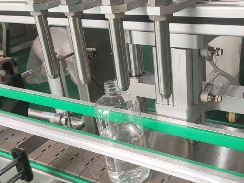
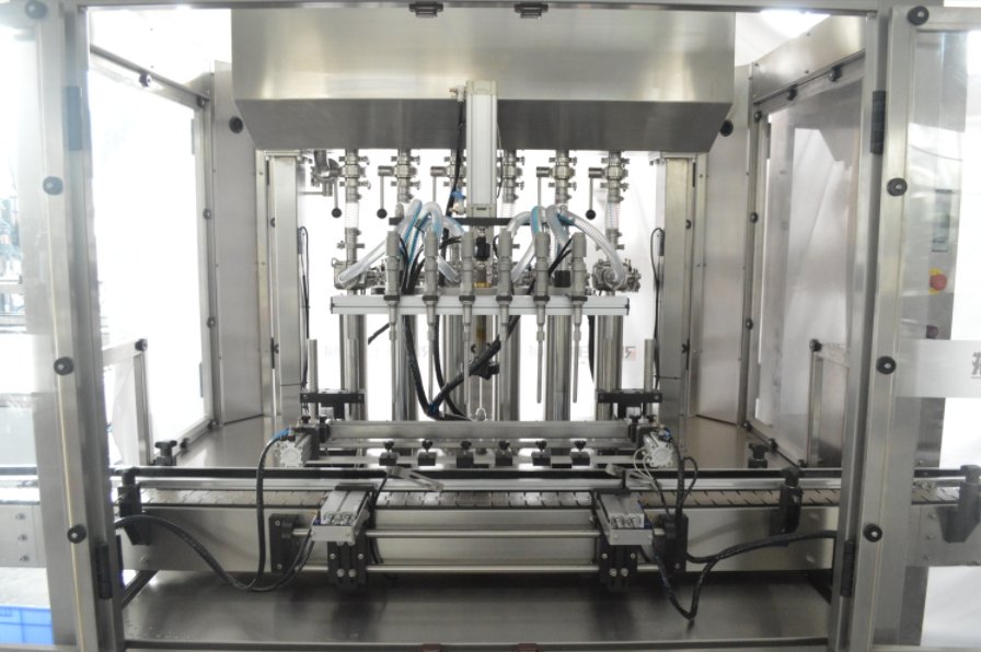
The tube filling process places a measured dose of cream, gel, ointment, paste or adhesive into a preformed tube through its open tail, then closes, codes and trims that tail before the tube is released. For equipment specifications and available configurations, see our tube filling machine page; this article focuses on the process itself, from tube positioning and dosing to sealing and inspection.
Every tube filling process follows the same logic, but the details change with three variables: how the product flows, what the tube is made of, and how the tail is closed. Plastic and laminate tubes are welded with heat or ultrasonic energy. Aluminum tubes are folded and crimped mechanically. The sections below explain each stage, how the stations stay in step with one another, and how fill and seal quality are verified.
Tube Filling Process at a Glance
| Stage | What Happens | Main Control Point |
|---|---|---|
| 1. Tube loading | Empty tubes are placed cap-down in holders, with the open tail facing up | Consistent tube supply and correct holder size |
| 2. Orientation | The tube rotates until a sensor detects its printed registration mark | Sensor detection and rotation accuracy |
| 3. Internal preparation | Filtered air, sometimes with extraction, removes loose particles where required | Clean, dry air and controlled extraction |
| 4. Product feeding | Product travels from the hopper or supply system to the dosing unit | Stable temperature, flow and hopper level |
| 5. Dosing | A measured quantity is dispensed into the tube | Dose setting, nozzle position and timing |
| 6. Cutoff and tail control | Flow stops cleanly and the nozzle withdraws without contaminating the tail | Cutoff design, withdrawal timing and headspace |
| 7. Closing the tail | The tail is welded (plastic, laminate) or folded and crimped (aluminum) | Heat or energy input, pressure, time, cooling or fold geometry |
| 8. Coding | Batch, date or lot information is embossed or printed | Code content, legibility and position |
| 9. Trimming | Excess material above a welded seal is cut to a clean edge | Even cut without damaging the seal |
| 10. Inspection and discharge | Nonconforming tubes are rejected; accepted tubes leave the machine | Defined checks for fill, seal, code and appearance |
Not every line includes every stage. Unprinted tubes may skip orientation, many lines omit internal air cleaning, and aluminum tubes are not trimmed the way welded tubes are.
How a Tube Moves Through the Filling Line
Most automatic lines move tubes in an indexing pattern: the transport advances one position, stops, and every station works on the tube in front of it during that pause. While one tube is being filled, the tube behind it is being oriented and the tube ahead of it is being sealed. A tube therefore spends one full filling cycle at each station, and a completed tube leaves the machine every cycle. This shared, step-by-step motion is the core of the tube filling machine working principle.
This has a practical consequence for the tube filling process. The length of each cycle is limited by the slowest station. A large dose of a thick product, or a seal that needs more heating or cooling time, sets the pace for every other station on the machine.
Three transport layouts are common:
- Rotary indexing tables carry holders on a turntable, with stations arranged around its circumference. The layout keeps every station within reach of a central drive.
- Linear transport systems move holders along a straight or oval chain. The longer path leaves room for extra stations, additional filling heads or inspection zones.
- Semi-automatic units follow the same filling and closing sequence, but an operator places each tube and removes the finished pack, so the loading rhythm depends on the person rather than the indexer.
Step-by-Step Tube Filling Process
Step 1: Loading Empty Tubes
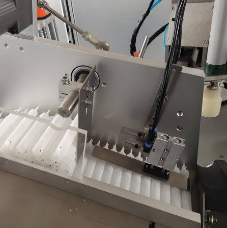
Collapsible tubes arrive with the cap already fitted, so they are filled from the other end. Each tube is placed cap-down in a holder, sometimes called a puck or cup, with the open tail facing up. On automatic lines a feeder separates tubes from a magazine or hopper and transfers them into holders one at a time; on semi-automatic units the operator places them by hand.
The holder must match the tube diameter closely enough to keep the tube upright and centered under the nozzle without deforming it. Loading stays reliable when tube dimensions are consistent, rims are undamaged and the supply never runs empty. Bent, oval, dented or wrongly sized tubes may not seat properly, and a poorly seated tube can cause a stoppage several stations later.
Step 2: Tube Orientation and Registration
Printed tubes carry a small registration mark, often called an eye mark. At the orientation station, the holder rotates the tube while a photoelectric sensor or camera watches for that mark. When the mark is detected, rotation stops at a programmed angle.
Orientation matters because the tail is closed flat. The seal line, the embossed code and the front artwork all need a fixed relationship to one another, or finished tubes will show crooked seals and misplaced codes. Unprinted tubes may skip this step. Transparent, metallic, reflective or low-contrast tubes can be harder to read and may need a different sensor or a vision system. On some machines, a tube that fails orientation is flagged and rejected rather than filled.
Step 3: Internal Tube Preparation
In some versions of the tube filling process, the line blows filtered air into each empty tube, sometimes combined with vacuum extraction, to remove loose particles from tube manufacturing, transport or storage. The air supply must be clean and dry. Moisture, oil or unfiltered air would add contamination instead of removing it. Whether this step is needed, and how it is validated, depends on the product, the tube material and the facility’s quality system.
Step 4: Product Feeding and Conditioning
Before it can be dosed accurately, the product has to reach the dosing unit in a consistent condition; in the tube filling process, dose accuracy starts here rather than at the pump. Depending on the formulation, the feed system may include a jacketed or heated hopper, gentle agitation, a heated product path, controlled pressure, vacuum deaeration, a sanitary transfer pump, and level sensors that keep the hopper between minimum and maximum limits.
Temperature has a strong effect on creams, gels, ointments, adhesives and pastes. A small change in temperature changes viscosity, which changes how the product moves through the pump and nozzle and therefore how much reaches each tube. Trapped air has a similar effect, because a pocket of air takes up volume that should be product.
Step 5: Measuring and Dispensing the Product
Dosing is the center of the tube filling process. A volumetric dosing unit, commonly a piston pump, draws a set volume of product and pushes it through the nozzle. Servo-driven pistons, rotary lobe, gear and progressive cavity pumps are also used, depending on how the product flows and whether it is abrasive, stringy or contains particles. Dose size is set by piston stroke or pump displacement, so on volumetric systems the fill weight depends on product density staying constant.
A typical dispensing sequence runs as follows:
- The tube arrives under the filling station.
- A sensor confirms that a tube is present in the holder.
- The nozzle descends into the tube to a programmed depth.
- The dosing unit dispenses the set quantity.
- On many machines, the nozzle rises as the product level rises.
- Flow slows near the end of the dose.
- A shut-off closes the flow path.
- The nozzle retracts before the tube indexes forward.
Filling from near the bottom and rising with the product level, often called bottom-up or diving-nozzle filling, reduces trapped air, splashing and contact between product and the upper tube wall.
Step 6: Controlling Nozzle Cutoff and Seal-Area Cleanliness
The moment the dose ends is as important as the dose itself. If flow does not stop cleanly, a string or drop of product can fall onto the inside of the tail as the nozzle withdraws. Product left in the seal area can cause weak welds, channels, leaks, poor appearance and rejects.
Clean cutoff depends on several factors working together: a positive shut-off valve or suck-back action at the nozzle, correct fill height, controlled withdrawal speed, and enough headspace between the product surface and the closing zone. Stringy products such as some adhesives are the most demanding. Persistent dripping should be traced to its cause rather than hidden by reducing the dose.
Step 7: Closing the Tube Tail
At this point in the tube filling process, the closing method is set by the tube material.
Plastic tube sealing
In hot-air sealing, a nozzle enters the open tail and directs heated air onto the inner surface without touching the product. Once the inner layer has softened, the tube moves to the closing station, where jaws press the walls together and the seal is cooled under pressure, often with cooled jaws. In ultrasonic sealing, a horn and anvil clamp the tail while high-frequency vibration generates heat at the interface between the two walls, so the weld forms where the surfaces meet rather than being heated from outside. The process variables include heat or energy input, exposure time, jaw pressure, cooling time, tube position and machine speed.
Laminate tube sealing
Laminate tubes are also welded, by hot air, ultrasonic or high-frequency energy, depending on their structure. The inner sealing layer has to reach welding condition without damaging the barrier layer or the printed outer surface. Two laminates that look identical can need different settings, so seal parameters are developed for the actual tube specification rather than copied from another tube.
Aluminum tube folding and crimping
Aluminum tubes are not melted shut. Folding tools flatten the tail, fold it one or more times and crimp the fold to lock it. Common closures include single, double and triple folds, saddle folds and plain or serrated crimps. The choice depends on the tube, the product, the required appearance and the closure specification.
Step 8: Applying Batch Codes
Coding usually happens at or just after the closing station. On welded tubes, a common method is embossing the code into the seal with characters set in the jaws, so code and seal form in the same stroke. Inkjet, laser and thermal-transfer systems are also used. Typical information includes batch or lot number, manufacturing date and expiry date. The code must be complete, legible and in the right position, which is one reason orientation in Step 2 matters. A vision system can confirm code presence, content and position.
Step 9: Trimming the Tube Tail
On welded plastic and laminate tubes, a cutter removes excess material above the seal and leaves a consistent edge. The finish can be straight, rounded at the corners, contoured, or shaped with a hanging hole, depending on the tooling. A good trim leaves even tube lengths and no sharp edges. A poor one can leave fragments or cut into the seal itself. Aluminum tubes finish at the fold and crimp, so they are not trimmed in the same way.
Step 10: Inspection and Discharge
The final stage of the tube filling process checks each tube against its defined requirements before discharge. Depending on configuration, checks can include tube presence and orientation, fill completion, tail cleanliness, seal formation, trim quality, code presence and tube height, plus checkweighing and vision inspection. A reject device diverts nonconforming tubes into a separate, controlled container so they cannot mix with accepted output. Accepted tubes leave on a conveyor or transfer directly to cartoning or other downstream equipment.
How Filling Stations Stay Synchronized
Because every station works on a different tube at the same moment, the tube filling process depends on precise timing between them. On mechanically driven machines, a main drive turns a set of cams, and each cam profile sets when a station moves and for how long. On servo-driven machines, individual motors follow electronic motion profiles, so a station’s timing can be changed through settings rather than by replacing a cam.
Sensors and interlocks protect the sequence:
- No tube, no fill: the dosing unit does not dispense if the holder at the filling station is empty.
- Orientation check: a tube whose mark is not found can be flagged for rejection instead of being filled.
- Supply monitoring: level sensors keep the product hopper and the tube supply within limits.
- Fault stops: guard doors, jams and misfeeds stop the cycle before damage spreads to later stations.
Product recipes stored in the controller hold settings such as dose volume, nozzle depth, seal temperature or ultrasonic parameters, and code content, so the same process can be repeated from one batch to the next. Not every machine includes every safeguard, and the exact logic varies between designs.
How Tube Material Changes the Sealing Process
Welding and folding are different physical events, which is why one closing method cannot simply be swapped for another.
- Plastic tubes: polyethylene and similar thermoplastics soften when heated and fuse when pressed together. The weld forms as the softened inner surfaces flow into each other and then solidify during cooling. Too little heat leaves an incomplete bond; too much can deform or thin the tail.
- Laminate tubes: a laminate combines sealable plastic layers with a barrier layer, such as aluminum foil or a barrier polymer. Only the inner sealing layer needs to melt. The barrier and outer print layers must survive the heat, which narrows the usable process window compared with plain plastic.
- Aluminum tubes: aluminum does not melt and fuse at sealing temperatures. Instead it can be folded and holds its shape once bent, so the closure is made mechanically. An inner lacquer or sealant coating can help the fold seal more tightly, but the closure still depends on fold geometry and crimp pressure, not on heat.
Newer mono-material and recycled-content tubes may behave differently from conventional structures under heat and pressure, so their seal settings are typically developed and verified for the specific tube.
How Fill Consistency and Seal Integrity Are Checked
Fill consistency in the tube filling process is affected by product density and viscosity, temperature, entrained air, hopper level, the condition of pumps, pistons and valves, nozzle cutoff, tube dimensions, machine speed and calibration. Visible fill height is not a reliable measure, because tube dimensions and tare weights vary. Where net weight matters, fills are checked by weighing tubes and subtracting the tare weight of empty tubes. Some lines weigh filled tubes inside the machine and use the result to adjust the dosing unit. Checks are most meaningful when they use the actual product, the intended tube and normal production speed.
Seal integrity depends on tube material, wall structure and tail thickness, heat or energy input, exposure time, jaw pressure, cooling time, fold geometry, tool alignment, tube position, speed and any product left in the seal area. A seal that looks good can still contain a channel or weak spot, so visual inspection alone does not prove seal integrity. A quality plan typically combines in-line checks with offline tests suited to the product and tube, such as dimensional checks, leak tests, burst tests and peel or seal-strength tests, using acceptance criteria defined in advance.
When fills drift or seals start to fail, the cause is usually one of the variables above. For fault patterns and how to trace them, see our guide to common tube filling and sealing machine problems.
Routine Process Checks Before, During and After a Run
A consistent tube filling process also depends on how a run is set up and closed down:
- Before production: confirm the recipe and format parts, check guards and safety devices, inspect the hopper, pump, hoses, nozzle and seals, verify holders and sensors, then run test tubes and confirm fill quantity and seal quality.
- During production: monitor fill weights, tail cleanliness, seal and trim consistency, product temperature and hopper level, and record alarms, rejects and stoppages.
- After production: remove leftover product safely, clean approved product-contact parts, inspect the nozzle and cutoff valve, clean holders and sensors, check sealing jaws, folding tools and cutters, and record faults and replaced parts.
Work in guarded, electrical, pneumatic, heated, ultrasonic or moving areas should be done only by trained, authorized personnel. Detailed procedures are covered in our cleaning and maintenance guide for tube filling and sealing machines.
Frequently Asked Questions About Tube Filling Process
What are the steps in the tube filling process?
The main steps are loading the empty tube, orienting it by its printed mark, optional internal air cleaning, feeding and dosing the product, cutting off flow cleanly, closing the tail by welding or folding, coding, trimming welded tails, and inspecting and discharging the finished tube.
How are tubes positioned before filling?
Each tube sits cap-down in a holder sized to its diameter. For printed tubes, the holder rotates the tube until a sensor finds the registration mark, then stops it at a set angle so the seal, code and artwork line up.
How is the correct amount of product dispensed?
A volumetric dosing unit, often a piston pump, moves a set volume through the nozzle on each cycle. Consistency depends on stable product temperature and density, an air-free supply, a clean cutoff and regular verification by weighing.
Why are tubes filled from the tail end?
Collapsible tubes are supplied with the cap already fitted, so the only open end is the tail. Filling through the tail lets the same opening be closed immediately afterward.
How are plastic tubes sealed after filling?
The inner surface of the tail is softened by hot air or by ultrasonic vibration, then jaws press the walls together and the seal cools under pressure to form a welded closure.
Why are aluminum tubes folded instead of heat sealed?
Aluminum does not melt and fuse at sealing temperatures. It can be folded and holds its shape once bent, so the tail is flattened, folded and crimped mechanically.
How is fill consistency checked?
By weighing filled tubes and comparing net weight with the target after allowing for empty-tube tare variation. Some lines weigh tubes in the machine and feed the result back to the dosing unit.
Conclusion
The tube filling process is a sequence of tightly linked stations: load, orient, prepare, feed, dose, cut off, close, code, trim and inspect. Each stage depends on the one before it. Accurate orientation places the seal and code correctly, clean cutoff protects the seal area, and the tube material decides whether the tail is welded or folded. Understanding how tube filling works station by station makes it easier to read process settings, interpret rejects, and judge what a filling line needs in order to run consistently.